Add Modbus registers
This guide shows how to add registers to monitor in ModbusScope.
Before you start
You must have at least one connection and one device configured. See Configure a TCP connection or Configure an RTU connection.
Steps
Click Register Settings in the toolbar.
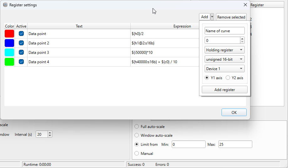
Click Add to insert a new register row.
In the Expression column, enter the register address using
${...}syntax (e.g.${40001}). See Reference: Register syntax for all supported forms.In the Name column, enter a label for the graph legend.
In the Color column, pick a line color.
In the Data type column, select the type that matches your device (
16b,s16b,32b,s32b,f32b). For coils and discrete inputs, the type is ignored.In the Y-axis column, select
Y1orY2.Repeat steps 2–7 for each register.
Click OK.
Result: The registers appear in the main window. They will be polled when you click Start Logging.
Tips
To reference a specific device, add
@DEVICEto the expression (e.g.${40001@2}reads from device 2). Device 1 is used by default.To calculate or combine values, use an expression instead of a bare address. See Write expressions.
Importing registers from a
.mbcfile is faster than adding them by hand. See Import from MBC file.Consecutive register addresses are read in a single Modbus packet. Gaps between addresses split the request and slow down the poll rate. See Optimize poll rate.